How to connect Ubique Panel with an Arduino
Goals
- Assume Arduino is the main control board. The data collected by the Arduino board will be shown on the Ubique Panel.
- The Ubique Panel interacts with the users and takes commands from the users. The Ubique Panel then sends the communication to the Arduino for further actions.
Preparation
-
ADE: Please download from IOT Website
-
Arduino IDE: Please download from Arduino Website
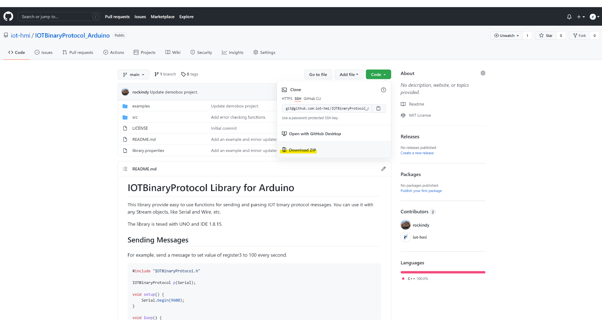
Step 1: Download IOT Binary Protocol
-
Please go to IOT Github
-
Download the ZIP file
-
Please follow README.md for setting up
Step 2: Open Arduino IDE
-
Please create a file folder and name it demobox_arduino
-
Download the ZIP file from Github
-
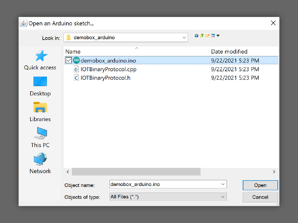
Copy IOTBinaryProtocol.cpp and IOTBinaryProtocol.h from src to demobox_arduino
-
Copy demobox_arduino.ino from examples to demobox_arduino
-
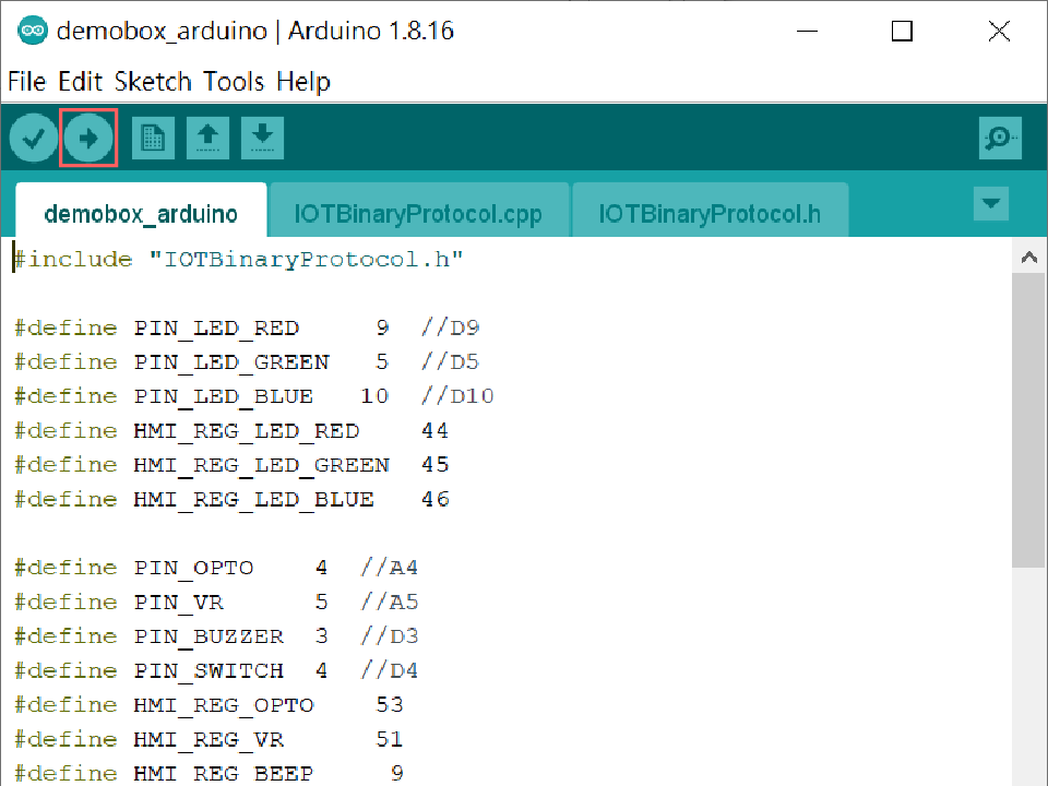
In Arduino IDE, open demobox_aruino.ino from demobox_arduino
-
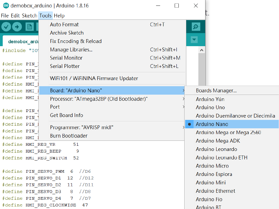
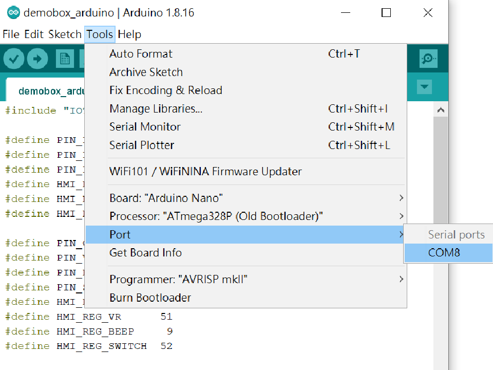
Select Arduino Nano
-
Use a USB cable to connect the Arduino Nano and the PC. Select the right processor and the serial port.
- Please select the right processor. Should there be questions, please refer to Arduino Website.
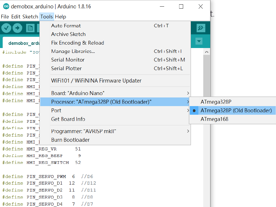
- If the serial port can not be found, please refer to ftdichip Offical Site to download the FT232 USB UART Driver.
-
Please cliclk ⇨ to download the Arduino program.
-
Disconnect the USB cable.
Step 3: Launch ADE
-
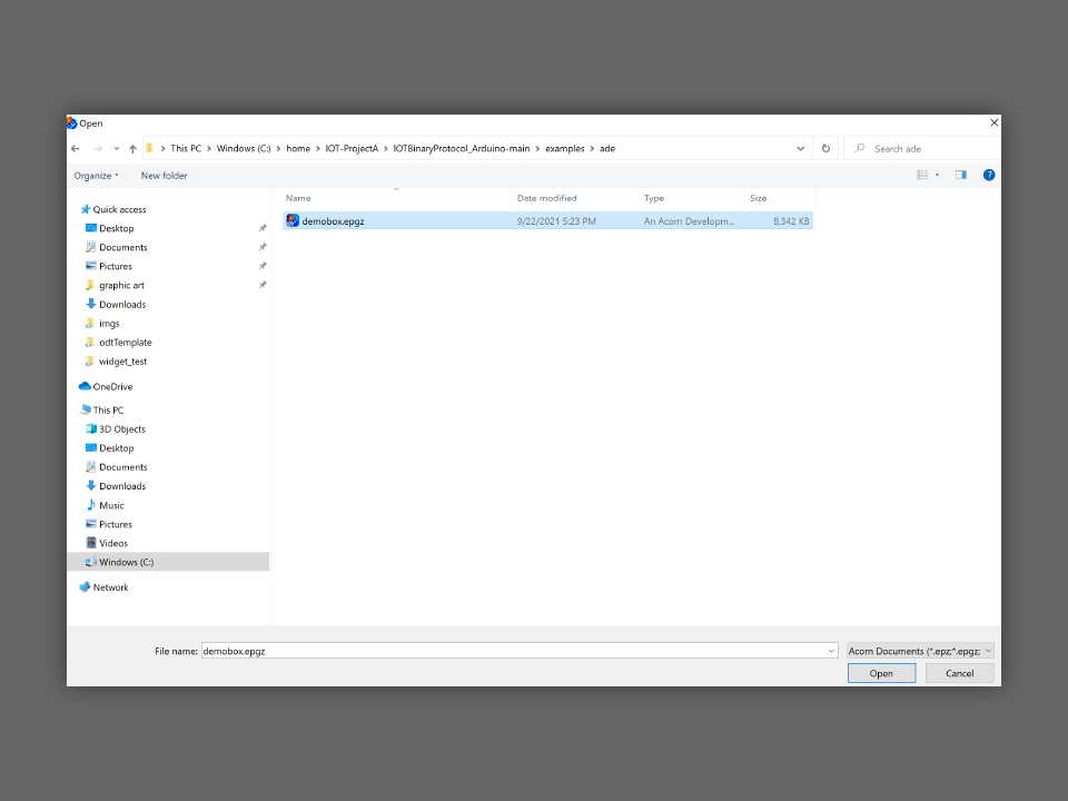
Open demobox.epgz from the examples > ade folder.
-
Connect the DC power cable with the Ubique Panel.
-
Turn on the power.
-
Use a USB cable to connect the Ubique Panel with the PC running ADE.
-
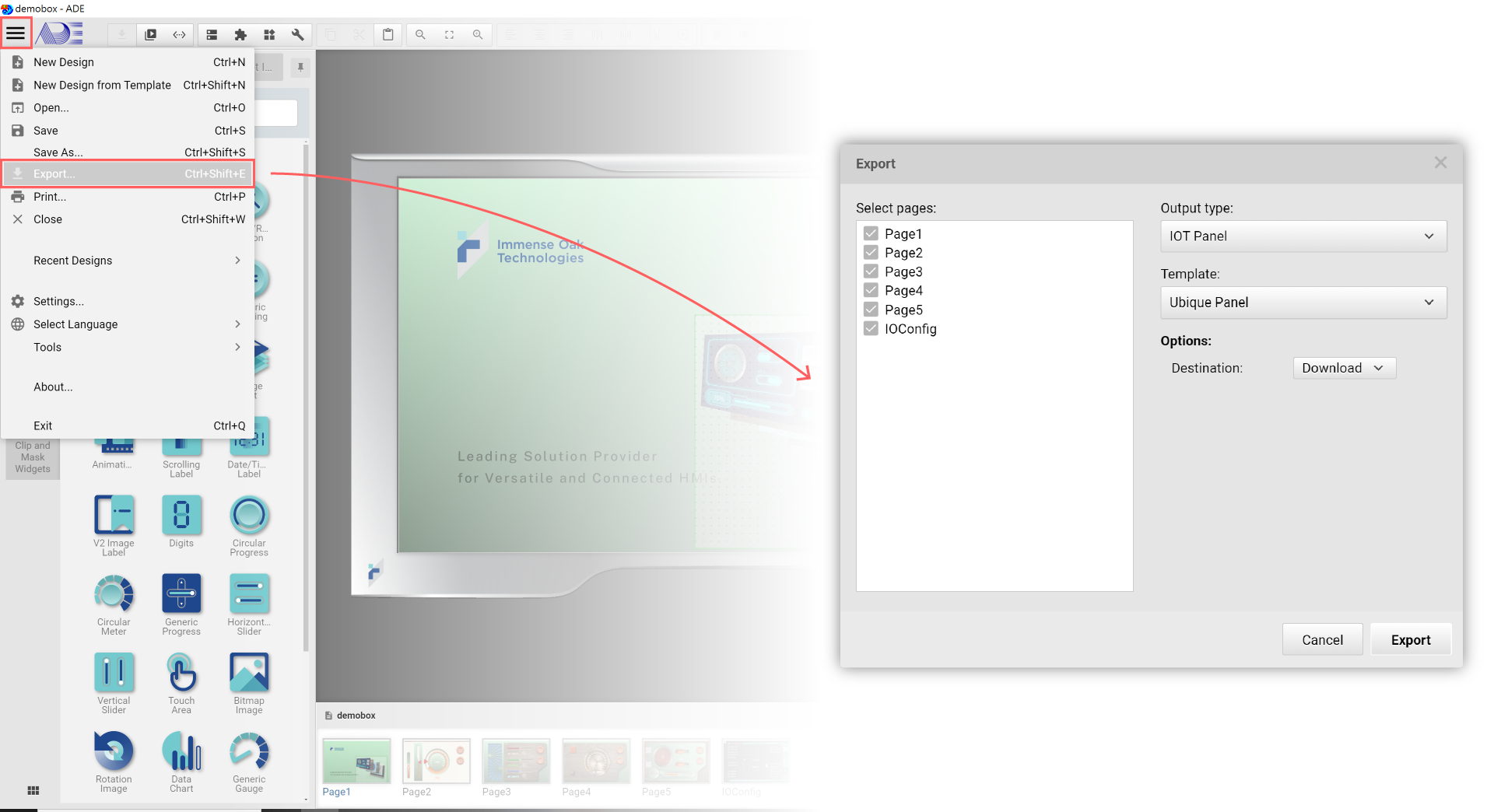
In System Menu, please click Export…
-
Disconnect the USB cable.
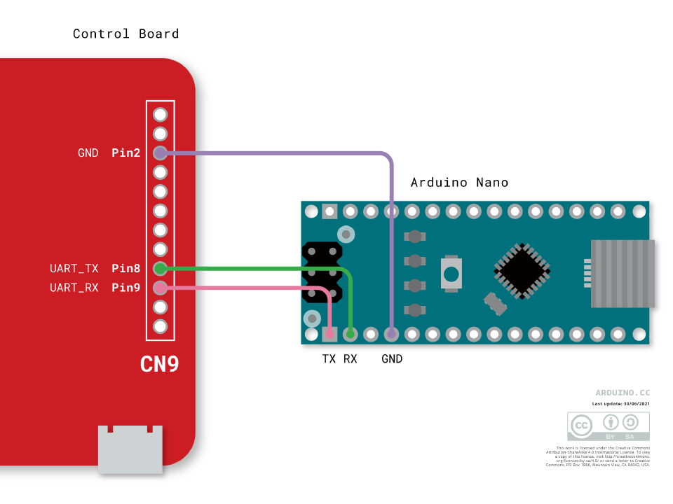
Step 4: Connect the Arduino board with the Ubique Panel
-
Please connect the Arduino board and the Ubique Panel with a Dupont Connector
-
Arduino Nano must have its own DC power supply.
-
Ubique Panel’s connector has 2.0mm pitch.
-