Modbus RTU Demo Project Explained
Goals
1. Describe this demo project in detail to help developers customize their own Modbus RTU protocol
2. Describe how to export this project to a Nexus Panel
Preparation
- Install and launch ADE: Please go to ADE Reference Manual for downloading ADE
- Download Modbus RTU Demo project: Please go to IOT Website download the demo project. Please make sure you download the demo project that fits your ADE version.
Step 1: Lauch ADE
Launch ADE:

Step 2: Open the demo project “ADE demo_modbus_rtu.epgz”
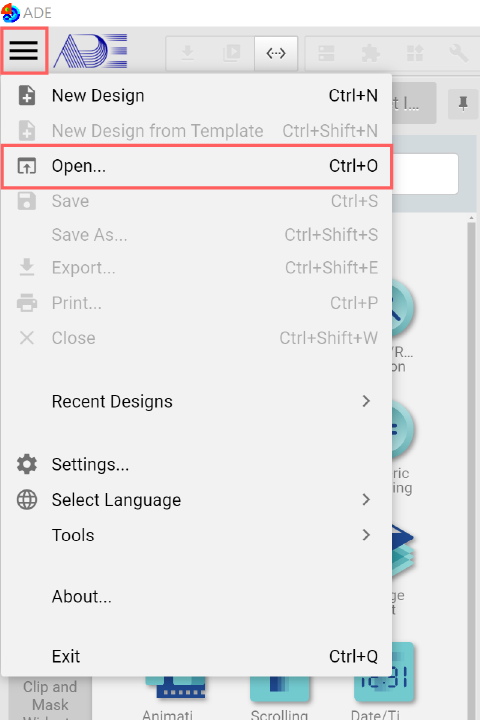
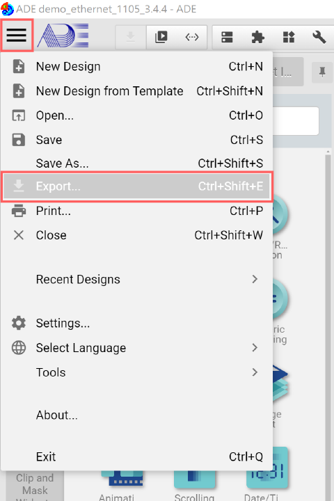
Click the System Menu, press Open and then choose "ADE demo_modbus_rtu.epgz".
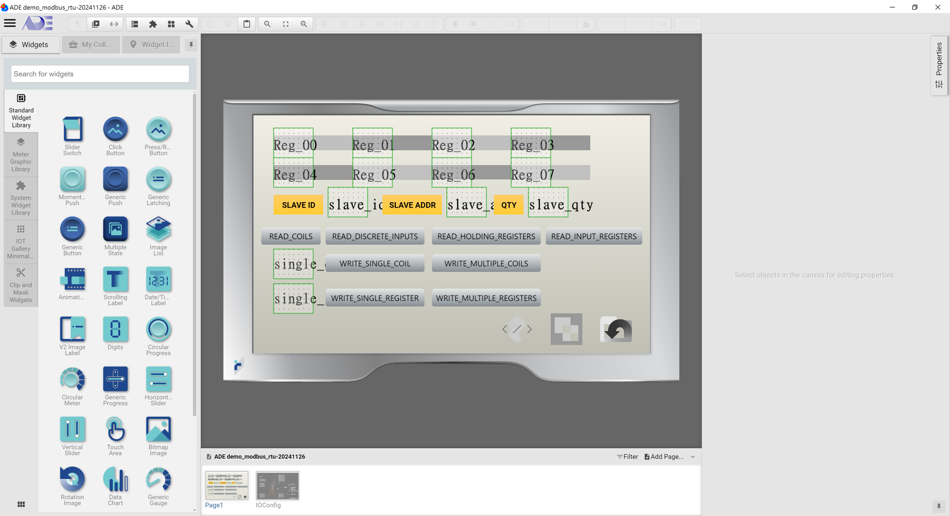
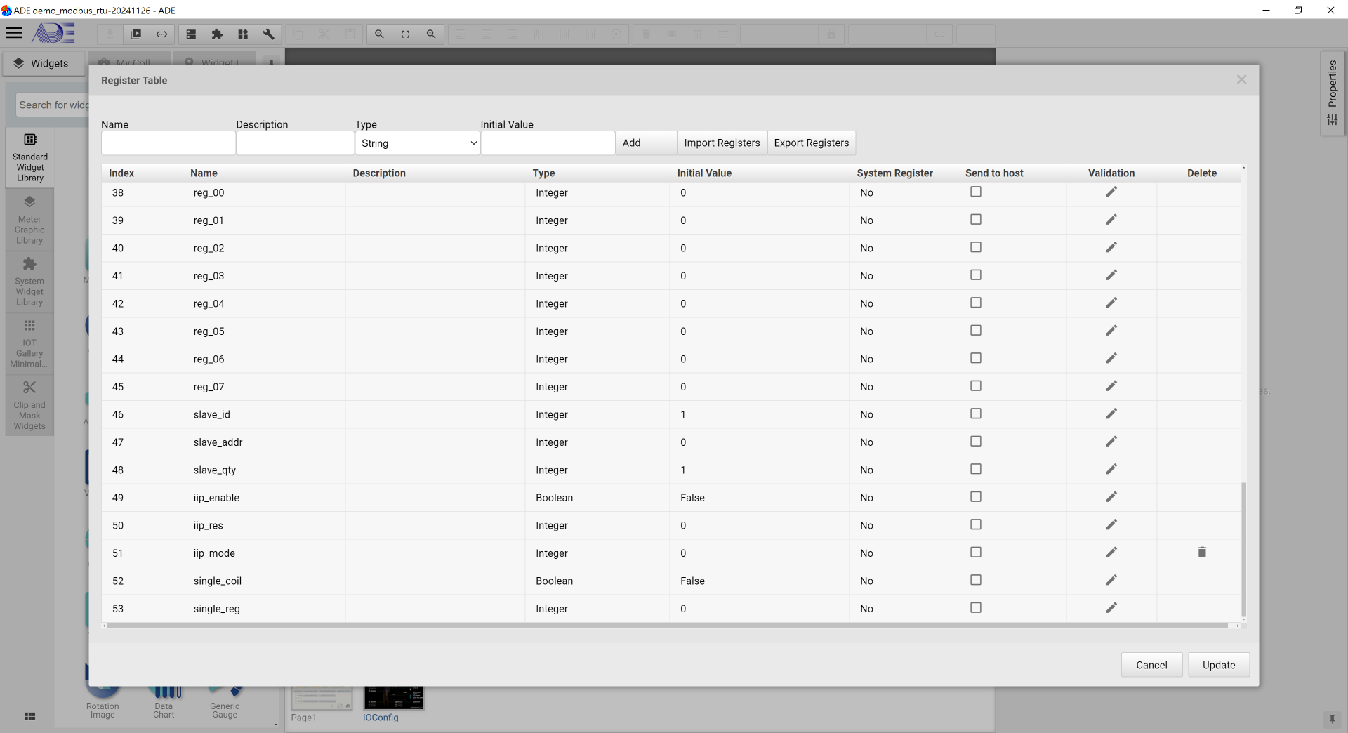
Once the project is successfully loaded, you will see:
Step 3: Demo Project Explained
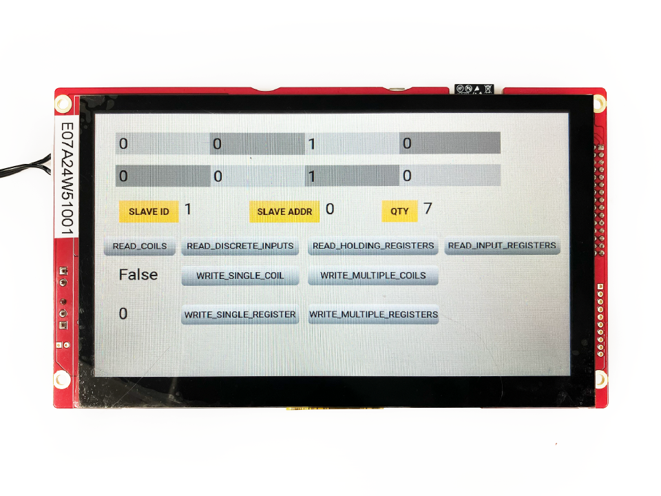
Page 1
| Code | Function Name | Description |
|---|---|---|
| 0x01 | Read Coils | Read ON/OFF status of discrete coils in the slave (0 or 1). |
| 0x02 | Read Discrete Inputs | Read the ON/OFF status of discrete inputs in the slave (0 or 1). |
| 0x03 | Read Holding Registers | Read the binary contents of holding registers in the slave (16 bits). |
| 0x04 | Read Input Registers | Read the binary contents of input registers in the slave (16 bits). |
| 0x05 | Write Single Coil | Writes a single coil to either ON or OFF. |
| 0x06 | Write Single Register | Writes a value into a single holding register (16 bits). |
| 0x0F | Write Multiple Coils | Writes each coil in a sequence of coils to either ON or OFF. |
| 0x10 | Write Multiple Registers | Writes values into a sequence of holding registers. |
-IFILE: modbus_rtu_protocol.py, modbus RTU function in Python codes.
-ICO_Modbus_RTU: Import mod bus RTU and init.
-INB_READ_COILS: Click to read the current status of Coils.

-IIP1: Popup Input Pad.
-ITA_slave_id: Click to enter the slave ID.
-ITA_slave_addr: Click to enter the slave address.

-Reg_00~07: Display the read register values.
-slave_id: Display the entered slave ID.
-slave_addr: Display the entered slave address.

-ITA_slave_qty: Click to enter the quantity of slave for connection.
-slave_qty: Display the entered slave quantity.
-INB_READ_DISCRETE_INPUTS: Click to read the status of coils in the slave (ON or OFF).
-INB_READ_HOLDING_REGISTERS: Click to read the holding register's value in the Slave (16 bits).
-INB_READ_INPUT_REGISTERS: Click to the contents of input registers in the slave (16 bits).
-single_coil: Display the status of a single coil (ON/OFF).
-ITA_single_coil: Click to enter the ON/OFF of a single coil.
-INB_WRITE_SINGLE_COIL: Click to write a single coil to either ON or OFF.
-single_reg: Display the entered register value.
-ITA_single_reg: Click to enter the register value.
-INB_WRITE_SINGLE_REGISTER: Click to write a value to a single holding register (16 bits).
-ITA_reg_00~07: Click to enter values for writing to the holding registers in the slave.
-INB_WRITE_MULTIPLE_COILS: Click to write a sequence of coils to either ON or OFF in the slave.
-INB_WRITE_MULTIPLE_REGISTERS: Click to write values into a sequence of holding registers in the slave.
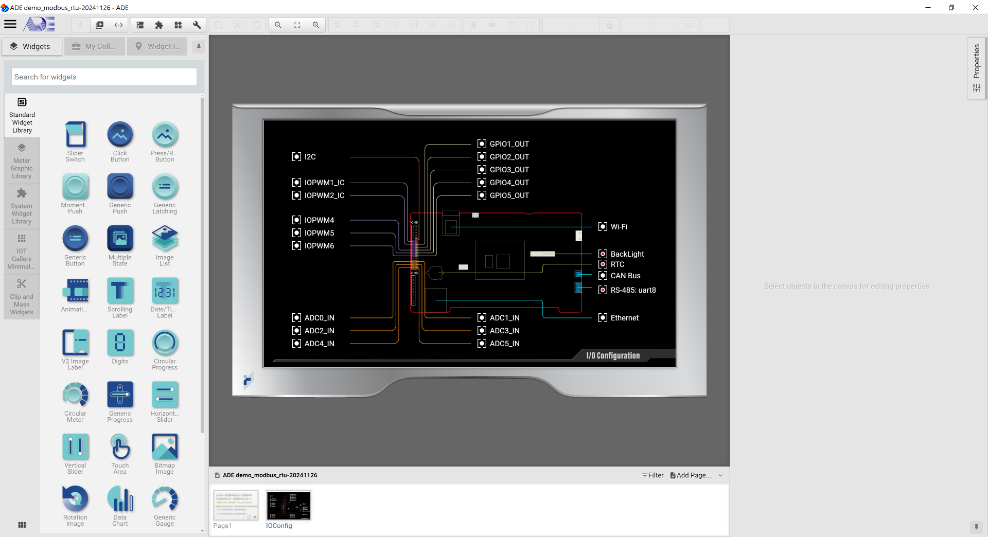
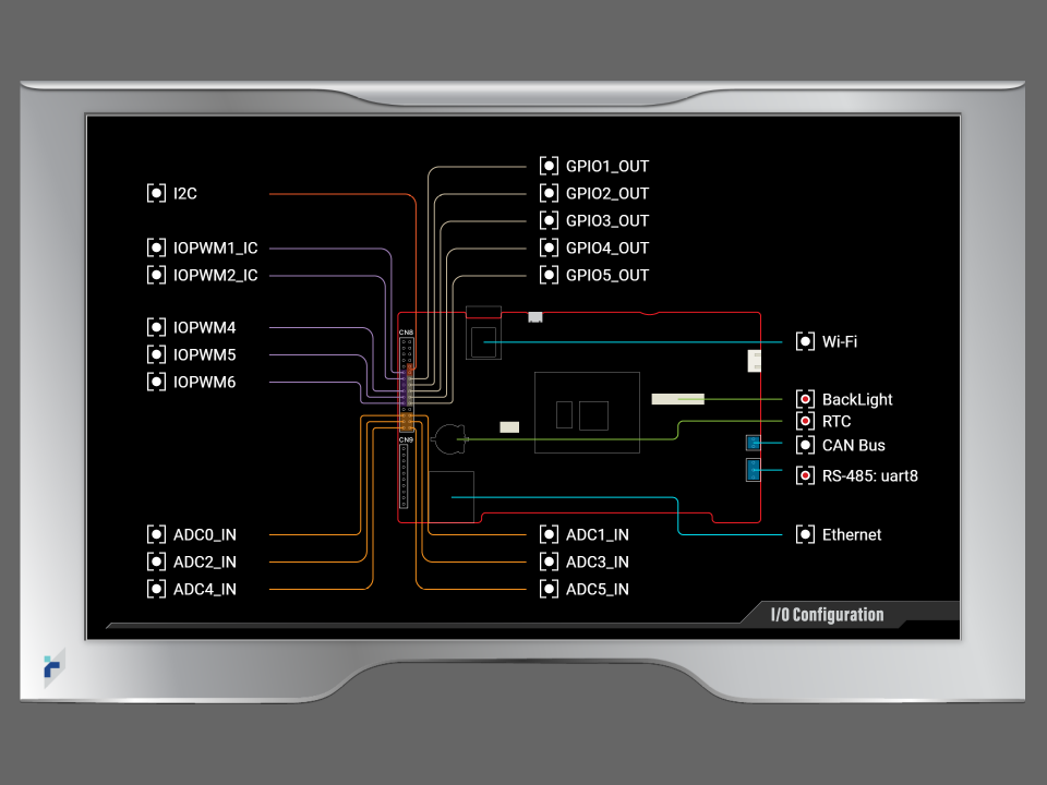
Page 2
Enable IO:

    -Backlight: The screen is locked after 180 seconds of inactivity.
    -RTC: Set the real time clock.
    -RS-485: uart8 : As shown in RS-485 Configuration, a call back function, com_rcv(data), is defined to procee or receive and display data from the com port.
       => Import File
            1. com.py
            -> com.py defines RS-485 initialization (including uart id, baudrate, buffer size and so on).
Step 4: Export Demo Project
It is recommended to run the demo project in the built-in simulator before exporting the project to an IOT product.
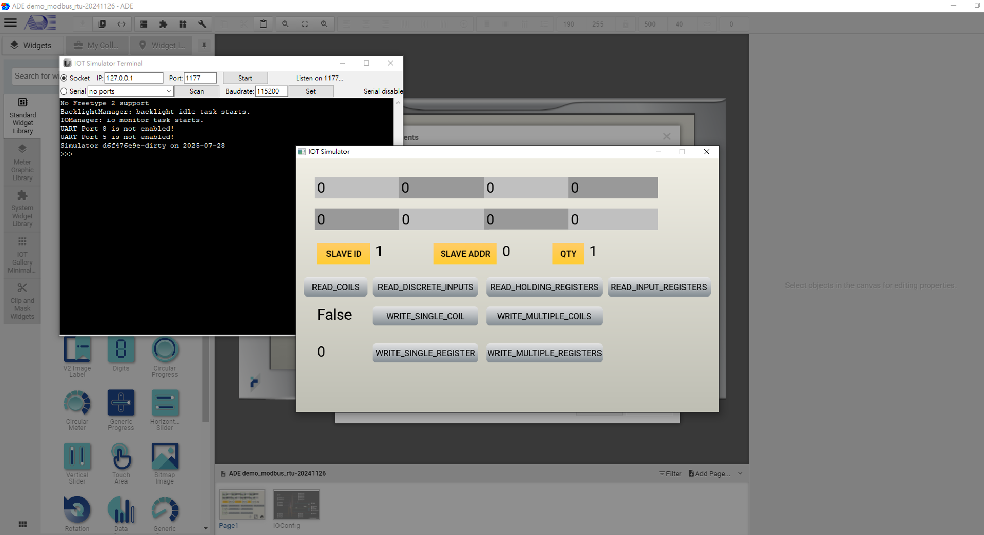
Launch the built-in simulator
Click "Launch Simulator" in the "Download" tool bar.
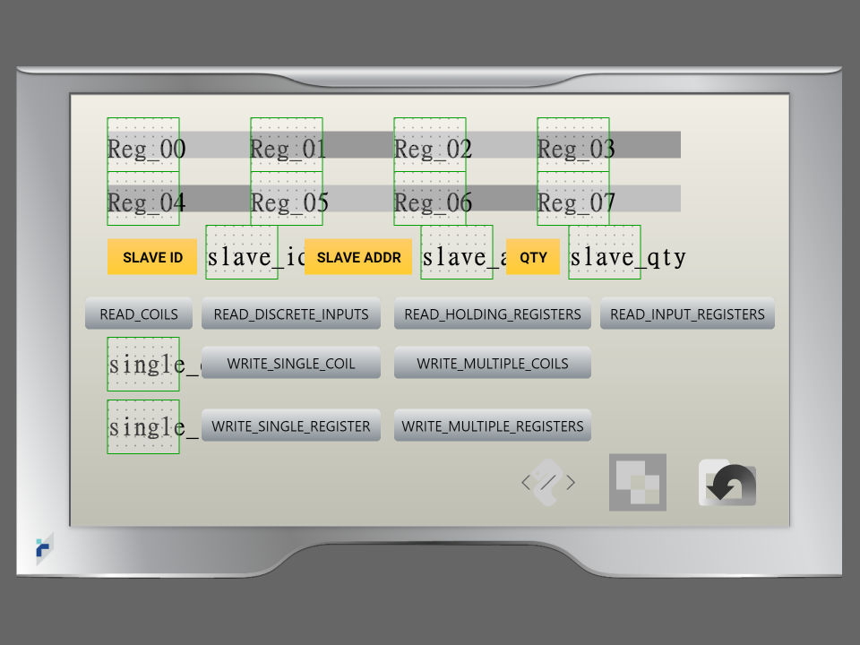
Once the simulator is launched successfully, users will see:
Export to an IOT panel
1. Please connect the panel with your PC with a USB cable. Then power on the panel.
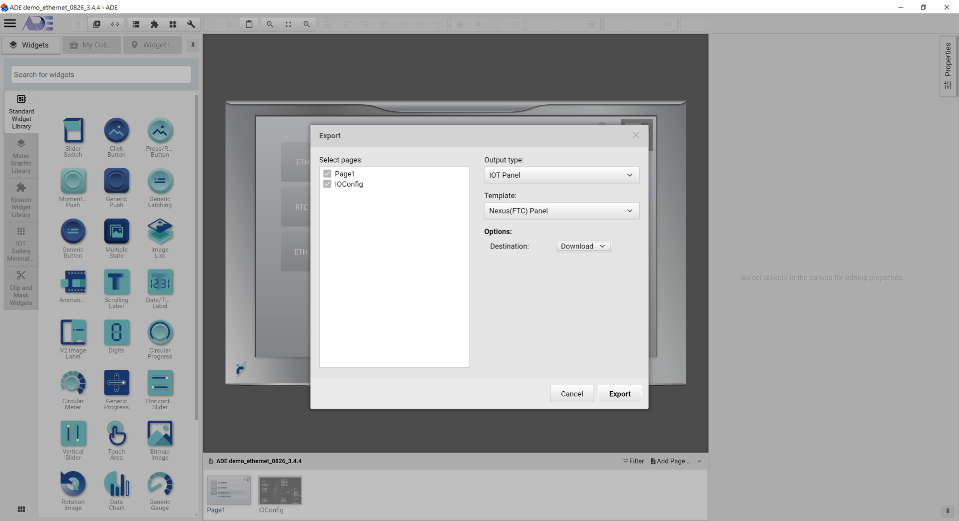
2. In ADE, export the demo project.
3. As shown, in the Export window, please select the Output Type to "IOT Panel", match the template to your target IOT panel and set Options to download. The click Export at the bottom.
1. Once Export is executed successfully, remove the USB cable.
2. Plead download the Modbus Slave application on a PC.
3. Please make sure the Serial Setting and the Slave ID must match.
4. Switch to a different mode to read and write the coils and holding registers.
5. The results are shown on the Panel as well as on the PC.
Conclusion
The demo project is to show how the basic Modbus RTU operations are done. Users can customize their own Modbus RTU communication based on the sample code offered in this project.